


Next: About this document
Up: No Title
Previous: Boolean Arithmetic and Switching
Instead of Boolean expressions, we can draw graphical presentations of
Boolean circuits, using the following three symbols for and,
or, inverse:

In various places, these objects are called ``switches,'' ``circuit
elements,'' ``logical elements,'' ``gates.'' Because and and
or are associative, it makes sense to allow arbritrary numbers
of inputs to these symbols. Invertors only make sense with one
input. The invertor symbol is not used very much. Instead, and
inversion is abbreviated as a small open circle, attached to an input
or the output of another gate. This leads to four additional
abbreviated symbols:
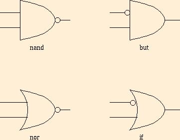
In principle, there are 16 ways to combine a single binary
and/or gate with negations: why did I only show 6? Can
you explain the slightly whimisical names ``but'' and ``if''?
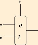
Another gate commonly used in circuits is the binary
multiplexor--a gate implementing the trinary operation with the
following table:

 uses the value of c to choose between
a and b. In other places,
  is written
`` if c then b else a.'' The symbol for a
mux gate looks like
A circuit is a graph made up of gates and connections between
them. The connections are drawn as lines (called wires), and
they are allowed to branch out. A solid circle shows where wires
connect: lines that merely cross do not connect. For example, here is
a circuit to compute
xor:
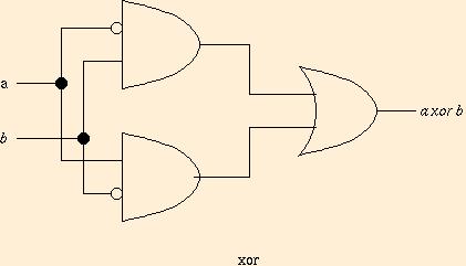
Circuits with no loops, such as the xor circuit above, are
called combinational circuits. They are just graphical
presentations of Boolean expressions, except that the output of a gate
may branch out to several gate inputs, avoiding repetition of
subexpressions in some cases. Sequences of assignments with Boolean
expressions on the right-hand sides correspond precisely to
combinational circuits.
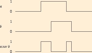
Circuits get more interesting when we consider their behavior over
time. Suppose that the value on each wire is a function from time to
0,1. The inputs and output in the xor circuit above might
look like:
Real electronic circuits will have varying delays for propagation of
values along wires, and strange intermediate values between 0 and 1
during transitions, so the true values of wires at every moment in
time can be hard to predict. But, if we keep the inputs steady, and
wait a bit, a combinational circuit will eventually produce an output
determined by the Boolean operations involved.
Circuits get really interesting when we let them have
loops. Think what happens when two nor gates feed back to one
another:

Cross-coupled nor gates have a history-dependent behavior. For
example:
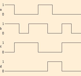
When a=b=1, c=d=0. When  , then c=b and
d=a. But, when a=b=0 the values of c and d depend on earlier
behavior. Try to describe the dependence, after studying the
example. What happens if a and b change from 1 to 0
simultaneously? In a real electronic circuit, with somewhat
unpredictable delays, the cross-coupled nor circuit has a
race condition, where the result depends on the delays.
The following circuit, based on the cross-coupled nor, is
called a latch. Why?

Convince yourself that when b=1, c=a; also when b=0, c has the
last value of a that occurred while b was 1. Notice that
 . There are other latch circuits. The one above is
often used in practice, because it works particularly well
electronically.
Two latches in a row provide a 1-bit memory element, called a
flip-flop:

Convince yourself that d has the value of a from the last time
that b changed from 1 to 0. How did c and d reverse their
roles from the latch circuit?
Flip-flops and latches use feedback loops to preserve a stable state
as long as certain conditions hold: they are a sort of 1-bit
memory. Other feedback loops can be pathological. What happens if we
try cross-coupled ors instead of nors?
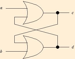
Once a 1 enters this circuit, c=d=1 forever. The circuit with one
or and one nor is even worse:

When b=1, c=a and d=0. When a=1 and b=0, we get c=1 and
d=0. But, when a=b=0, the circuit behaves like a buzzer, with c
and d alternating values at a speed determined by the electrical
delays in the feedback loops. Well designed computers don't contain
unstable circuits such as the or/nor buzzer. (Not quite
true. Every computer these days has a clock, which is a sort of
buzzer. But, the clock is not implemented with the same sort of
electronics normally used to implement Boolean circuits, since the
speed would not be very stable. Instead, a clock is a special circuit
using a crystal oscillator).


Next: About this document
Up: No Title
Previous: Boolean Arithmetic and Switching
Mike O'Donnell
Fri Jan 22 10:15:39 CST 1999


![]() uses the value of c to choose between
a and b. In other places,
uses the value of c to choose between
a and b. In other places, ![]() is written
`` if c then b else a.'' The symbol for a
mux gate looks like
is written
`` if c then b else a.'' The symbol for a
mux gate looks like


