Laboratory 4 will be collected from your GitLab repository on Thursday, April 22, 2021 at 11:59pm.
Preliminaries
We have pre-seeded your repositories with a template file named
lab4.rkt in a directory called lab4. To get started,
update your local repository.
cd cs151
git pull
assuming that cs151 is the name of your local repository.
At this point, if you do a ls command, you should see a directory
named lab4.
Open the lab4.rkt file in DrRacket.
Once you have opened your lab4.rkt file with DrRacket, go to the
Language menu, then select "Choose Language…", and then choose
"Determine language from source" from the popup menu on the lower
left edge of the application window.
You will notice that the lab4.rkt file begins with
the following code:
#lang typed/racket

;; CMSC15100 Spring 2021
;; Lab 4
;; <YOUR NAME HERE>

;; List your collaborators in a comment

;; include CS151-specific definitions
(require "../include/cs151-core.rkt")
(require "../include/cs151-image.rkt")

;; include testing framework
(require typed/test-engine/racket-tests)
You should replace "<YOUR NAME HERE> with your name.
Description
This week, you will practice programming with recursive data structures.
The lab4.rkt file contains definitions of a small 2D vector library and
a representation of paths. In this lab assignment, you will first
write a function to generate a fractal path and then functions to take a
path and draw it using DrRacket’s image functions.
2D Vectors
The lab4.rkt file contains the definition of the type of points/vectors
in the plane as well as a few useful utility operations on these points.
;; A (Vec2 x y) represents either a point or a vector in 2D space
;;
(define-struct Vec2
  ([x : Real]
   [y : Real]))

(: vec2-add : Vec2 Vec2 -> Vec2)
;; add two Vec2 values returning their sum
(define (vec2-add p1 p2) ...)

(: vec2-sub : Vec2 Vec2 -> Vec2)
;; subtract p2 from p1
(define (vec2-sub p1 p2) ...)

(: vec2-scale : Real Vec2 -> Vec2)
;; multiply the 2D vector v by the scalar s
(define (vec2-scale s v) ...)
Paths
The lab4.rkt file contains the following data definition for representing
paths:
;; A (Line p q) represents the line segment from point p to point q
(define-struct Line
  ([start : Vec2]
   [end : Vec2]))

;; A Path is either a Line or the Join of two Paths
(define-type Path (U Line Join))

;; A Join is the concatenation of two paths
(define-struct Join
  ([path1 : Path]
   [path2 : Path]))
The Dragon Curve
The first part of this exercise is to construct a Path value for a well-known
fractal curve called the Dragon Curve.
The Dragon Curve is a fractal curve that is made up of straight line segemnts. Each line segment is labeled as either a left or right edge (the root edge is labeled as a right edge by convention). Given a curve (i.e., path) at depth \(d\), we can generate the path at depth \(d+1\) by splitting each edge in the path using the following two rules, where the green dot represents the start of the line segment and the red dot represents the end:
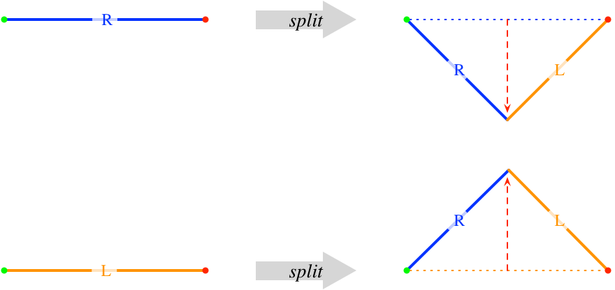
If \((dx, dy)\) is the vector from the start point of a line segment to its end point, then the vector from the start point to the split point for a left edge is given by the equation
and the vector from the start point to the split point for a right edge is given by
In your implementation, you should write two helper functions that compute the split points for left and right edges. The seed code defines a number of constants that you may find useful in implementing these functions.
(: split-left  : Vec2 Vec2 -> Vec2)
(: split-right : Vec2 Vec2 -> Vec2)
The following figure illustrates how we can generate a depth 3 Dragon Curve by iterative application of the rules.
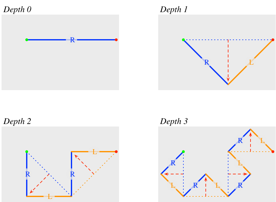
You should write a recursive function that generates the curve of given depth for a labeled edge:
(: dragon-curve : Integer Vec2 Edge-Label Vec2 -> Path)If the depth is 0, then the curve is just the line from start to
end. Otherwise, one splits the edge and joins the paths generated by
recursively calling dragon-curve.
Drawing Paths
The second part of the exercise is to implement support for converting a path
to an image.
You will define a function draw-path that takes a path and a color (specified
as a String) and returns an Image.
You should use the Racket image-library function
(: add-line : Image Real Real Real Real (U Image-Color Pen String) -> Image)
;; (add-line img x1 y1 x2 y2 color) adds a line segment with the given
;; color from (x1, y1) to (x2, y2) to the image img and returns the
;; resulting image.
to draw lines. Note that since this function adds a line to an existing image value, it most naturally works in a function that uses an accumulator to build up an image.
The tricky part of this code is mapping the coordinates of the path to the image’s coordinate space. The coordinates of an image have (0,0) for the upper-left-hand corner, have X increasing to the right, and Y increasing down. Paths, on the otherhand, use standard 2D coordinates (X increasing to the right and Y increasing up) and may include negative coordinate values. For example, consider the following path
(Join
   (Line (Vec2 -2 2) (Vec2 -1 2))
   (Join
    (Line (Vec2 -1 2) (Vec2 1 -1))
    (Line (Vec2 1 -1) (Vec2 3 3))))
The following figure illustrates the situation for this path, where the path is drawn in red and the extent of the image is denoted by the grey rectangle. The green coordinates represent the corners of the image in its coordinate system, while the maroon coordinates are the endpoints of the lines that comprise the path.
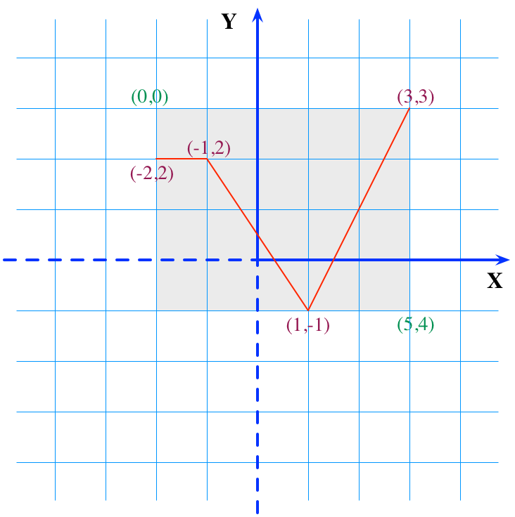
Let \(x_{min}\), \(y_{min}\), \(x_{max}\), and \(y_{max}\), be the minimum and maximum coordinate values for a path (e.g., the values for the path above would be -2 -1 3 3, respectively). Then we know that the width of the image will be \(\mathit{wid} = x_{max} - x_{min}\) and the height will be \(\mathit{ht} = y_{max} - y_{min}\).
The point \((x_{min}, y_{max})\) in 2D coordinates maps to (0,0) in the image’s coordinate system and the point \((x_{max}, y_{min})\) maps to \((\mathit{wid}, \mathit{ht})\). Thus, with a bit of algebra, we see that a point \((x, y)\) on the path can be mapped to \((x - x_{min}, y_{max} - y)\) in the image’s coordinate system.
Therefore, to draw a path, we need to first determine the
\(x_{min}\) and \(y_{max}\) values for the path
and then use those to offset the points that we feed to Racket’s add-line
function.
Write a helper function upper-left-corner that takes a Path value and returns
the the pair \((x_{min}, y_{max})\) as a Vec2 value.
(This value is the upper-left corner of the path’s bounding rectangle).
With this helper, you can implement the draw-path function.
Drawing the Dragon Curve
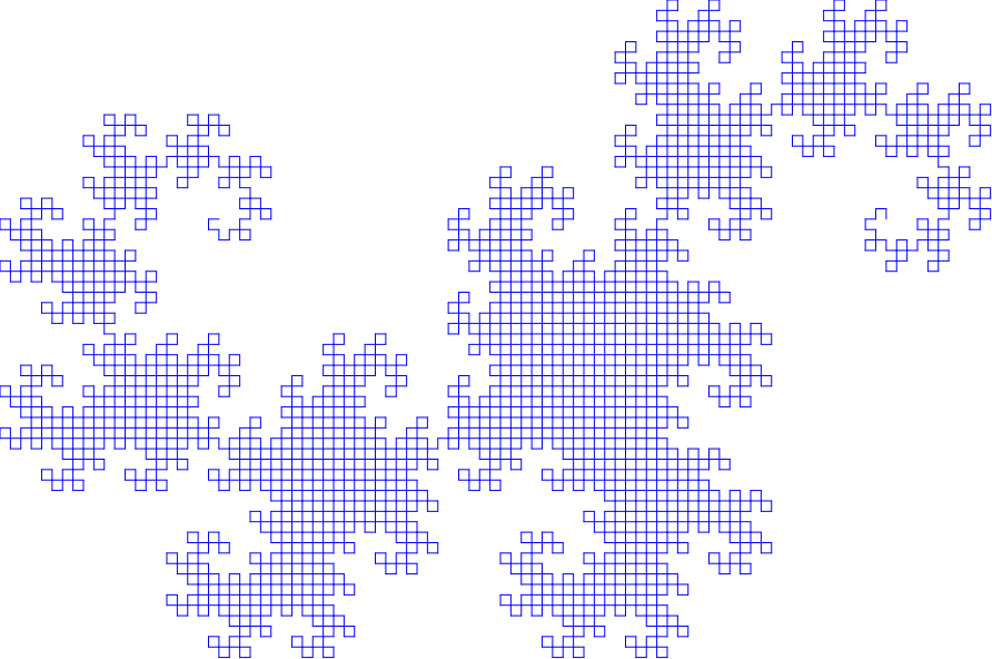
The final step of the lab is to combine your code that computes the path for a Dragon Curve with your path drawing code to implement the function
(: draw-dragon : Integer Vec2 Vec2 String -> Image)that takes an integer depth, start position, end position, and color, and returns a path representing the Dragon Curve of the specified depth. For example, the call
(draw-dragon 12 (Vec2 0 0) (Vec2 600 0) "blue")should produce the following image
Notes
Every function must be preceded by a type signature and a
purpose, and be followed by check-expect tests.
Make sure to include enough tests so that you can be confident
that your code does not have a bug.
For the functions that return images (e.g., draw-path and
draw-dragon), you will have to use eyeball tests.
On these points, we do not differentiate between
"helper functions" and "main functions" — all functions should have type signature, purpose comment,
and tests.
Submission Instructions
The assignment must be pushed to the GitLab server by Thursday, April 22, 2021 at 11:59pm; we do not accept late work. Remember that to submit your work you will have to add and commit it to your local repository, and then push your changes to the server. You can verify that your work has been submitted by using the web interface to the server.
We strongly recommend pushing your code after you write and test each function; do not wait to the last minute to discover that you cannot commit your work for some reason!!
Also, remember to include, in comments, the names of the other students you worked with during the lab meeting.