Class Meeting 03: Sensory-Motor Control
Today's Class Meeting
- Learning about sensory-motor control and PID control (here's a link to my slides)
- Writing code to enable Turtlebot3 to follow a line - here's a link to a sample solution for the line follower
What You'll Need for Today's Class
For today's class, you'll need the following tools/applications ready and running:
- The class Zoom room (access via Canvas)
- The class Slack (https://intro-robo-uchicago.slack.com)
- Your Ubuntu 20.04 programming environment
- We'll be using the starter repo/code from the class_meeting_03_line_follower repo
Sensory-Motor Control and PID Control
The content in this section summarizes the main points covered in today's lecture (here's a link to my slides).
One foundational concept in robotics is sensory-motor loops and control. The robot's sensor readings inform how it moves in its environment, which will then influence the next sensor readings from the robot, and the loop goes on. One of the most well known sensory-motor control methods is PID (Proportional Integral Derivative) control, which is depicted in the block diagram below:

The PID control function can be represented as follows:

Where Kp, Ki, and Kd, are the constant coefficients for the proportional, integral, and derivative terms; e(t) represents the difference between the goal (setpoint) and the sensor measurement (process variable). The three following graphs display how a system responds to a step change in the setpoint to each component of the PID controller separately and all the components combined at different values of Kp, Ki, and Kd.

Response of the process variable to a step change of the setpoint for different values of Kp. Source: Wikipedia.
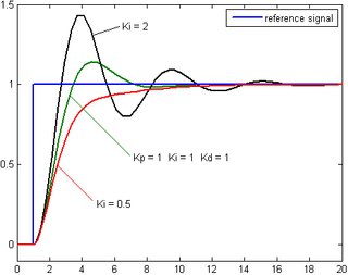
Response of the process variable to a step change of the setpoint for different values of Ki. Source: Wikipedia.
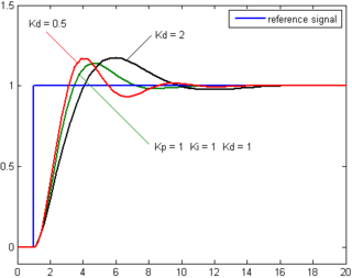
Response of the process variable to a step change of the setpoint for different values of Kd. Source: Wikipedia.
This YouTube video by Brian Douglas is a great resource providing a clear explanation of the PID controller.
Coding Exercise: Line Following with Turtlebot3
For this exercise you'll start in a breakout room of 4 students. You can find your breakout room assignments in this Google spreadsheet.
Getting Started
To get started on this exercise, update the intro_robo class package to get the class_meeting_03_line_follower ROS package and starter code that we'll be using for this activity.
$ cd ~/catkin_ws/src/intro_robo
$ git pull
$ git submodule update --init --recursive
$ cd ~/catkin_ws && catkin_make
$ source devel/setup.bash
Next, launch our prepared Gazebo world file. In one terminal, run:
$ roscoreIn a second terminal, run:
$ roslaunch class_meeting_03_line_follower robot_and_line_sim.launch
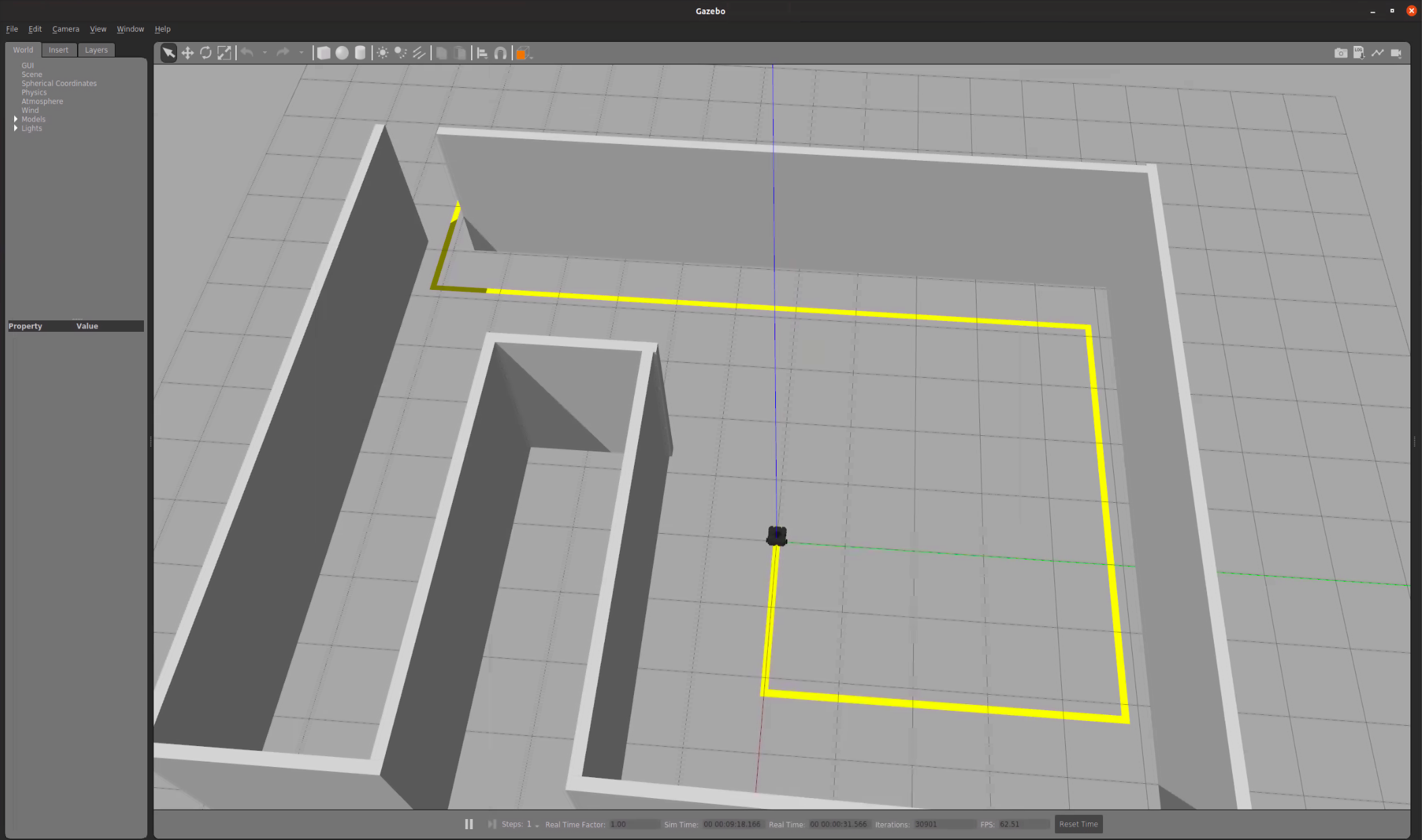
In Gazebo, you should see a Turtlebot3 at the beginning of a yellow line in an enclosed room (see image below). Your goal is to program the robot to follow the yellow line, writing your code in line_follower.py.
The starter code implements a helpful debugging window to help visualize the center of the computed yellow pixels. Once you've correctly identified the center of the yellow pixes, your window should look something like the following:

Understanding the Starter Code
In your group of 4, read through the starter code in line_follower.py. Discuss it together so that everyone in your group understands what's going on. We encourage you to look up what certain OpenCV functions do to better understand what's going on. Make sure that you all discuss and understand what the following variables represent and what values they will hold: h, w, d, cx, cy.
Implementing the Line Follower
To implement the line follower you'll work in pairs, where each pair will occupy the same Zoom room. Form pairs from your group of 4 (if you had a group of 3, you can stay together). Your pair can either stay in your breakout room or head to a new breakout room.
This programming exercise contains 2 main components:
-
Defining the range for what you will consider a "yellow" pixel in the image feed.
- OpenCV uses the following ranges for H, S, and V:
H: 0-179, S: 0-255, V: 0-255. As this OpenCV documentation suggests, you may find the following helpful (except you'll want to investigate yellow instead of green):green = np.uint8([[[0,255,0 ]]]) hsv_green = cv2.cvtColor(green,cv2.COLOR_BGR2HSV) print(hsv_green) - You may also find the "Swatches" section on the HSV Wikipedia page helpful. Remember, you'll have to convert from the HSV ranges in the Wikipedia page
H: 0-360, S: 0.0-1.0, V: 0.0-1.0to the numeric ranges OpenCV expectsH: 0-179, S: 0-255, V: 0-255.
- OpenCV uses the following ranges for H, S, and V:
-
Implementing proportional control to enable the robot to follow the yellow line. This will involve:
- Setting up a ROS publisher to control the movement of the robot.
- Computing an "error" term (the difference between the goal and the sensed reality). This most important part here is defining the "goal" and the "reality" comparison.
- Using the error term to determine how the robot moves in accordance with the principles of proportional control.
To run your code:
$ rosrun class_meeting_03_line_follower line_follower.pyOnce you've successfully implemented your proportional control line follower, it should look something like the following:
If you and your partner(s) finish early, feel free to use this time to work independently on your Warmup Project assignment.
Acknowledgments
The line-following exercise and code was taken and modified from Gaitech EDU. The world file used in this activity was modified from lfm.world from sudrag's line_follower_turtlebot Git repo.