Turtlebot3 Assembly & Setup
A Word of Caution
This page is NOT intended for student use. This page is designed for course staff to build and maintaing the turtlebots. If you are a student, please ensure you have permission from course staff before making any of the changes detailed on this page to any of the turtlebots.
Setup Checklist
- Turtlebot Assembly Tips
- OpenMANIPULATOR Arm First-Time Configuration
- Connecting the Pi to a Wi-Fi Network
- Attaching/Detaching the OpenMANIPULATOR Arm
Turtlebot Assembly Tips
Turtlebot3
- DO NOT TIGHTEN the screws too much.
- Page 10: When connecting one pair of waffle-plates to another, make that the seams connecting each waffle-plate are parallel to one other.
- Page 17: When attaching the wheels to the dynamixels, do not tighten the screws too much.
- Page 28: Mount the LiDAR further up than the manual specifies so that the arm can fit on (see completed Turtlebots for reference).
OpenMANIPULATOR Arm
- OpenMANIPULATOR Dynamixel 12: when putting the back piece onto the servo, you will need to break off a plastic piece where the cable should be threaded through.
- Make sure the placement of the marking on the servo horns is identical to the diagram PRIOR to screwing anything down onto it.
OpenMANIPULATOR Arm First-Time Configuration
After assembling an OpenMANIPULATOR arm, its servos must first be configured properly before it can be used. By default, all the arm motors are set to the same ID (1) and the wrong baud rate, which causes collisions when trying to detect them.
- Setup OpenCR with Arduino IDE using OpenCR 1.0 manual, “Arduino IDE” section
- Download Dynamixel Wizard 2.0 if not already installed.
- Connect a SINGLE motor (no daisy-chains in the arm) to the OpenCR module and DISCONNECT ALL OTHER MOTORS (the wheel motors!!)
- Open up Dynamixel Wizard 2.0 and update the firmware for that motor by following this tutorial. The arm Dynamixel model is XM430-W350, and the wheel motors are XM430-W210.
- Scan for connected Dynamixels using the “Scan” button on the top menu. If the scan does not turn up any results, you may need to change the scan options in the "Options" menu. By default, an unconfigured arm motor will have ID 1, be on Protocol 2.0, and have a baud rate of 57600 bps.
- Change the ID for the detected motor from 1 to 11/12/13/14/15 (whichever you're doing the procedure for). Click on the “ID” item, and find the ID # you want in the lower right corner. Click it and press “Save”.
- Change the baud rate to 1M (if not already 1M). Click on the “Baud Rate (Bus)” item, and find the 1 Mbps option. Click it and press “Save”.
- Disconnect the motor (both in the wizard by clicking “Disconnect” up top and physically disconnecting from the board) and repeat the steps for the remaining ones.
Connecting the Pi to a Wi-Fi Network
Connect a keyboard, mouse and monitor to the Pi. Attach the charging cable to the OpenCR board
to provide enough power for the Pi to boot with the peripherals attached.
Once Raspbian has loaded up, go to the wifi icon in the upper right corner of the screen and
connect to your wi-fi network of choice.
Use the ifconfig command and make a note of the IP address.
Assigning a Reserved IP Address
If the Pi is being set up for use on the intro-robo router, you can configure the router
to automatically assign it a specific IP address whenever it connects.
- Connect your computer to the
intro-robonetwork. - Enter
192.168.0.1into your web browser and log in to the router. - Go to the "Advanced" tab at the top of the page and select Network -> DHCP Server from the sidebar.
- Press "Add" under the "Address Reservation" section of the page.
- Get the Pi's MAC address using
ifconfig
Once you've set a specific IP address for a Turtlebot, make sure to set the ROS_HOSTNAME environment variable on the robot's Pi.
Attaching/Detaching the OpenMANIPULATOR Arm
Physical Attachment/Detachment
Follow these steps below:
- The arm can be attached and detached by first removing the top layer of the the Turtlebot. There are 10 screws around the perimeter of the top layer that you will need to remove with a Phillips head / cross screwdriver.
-
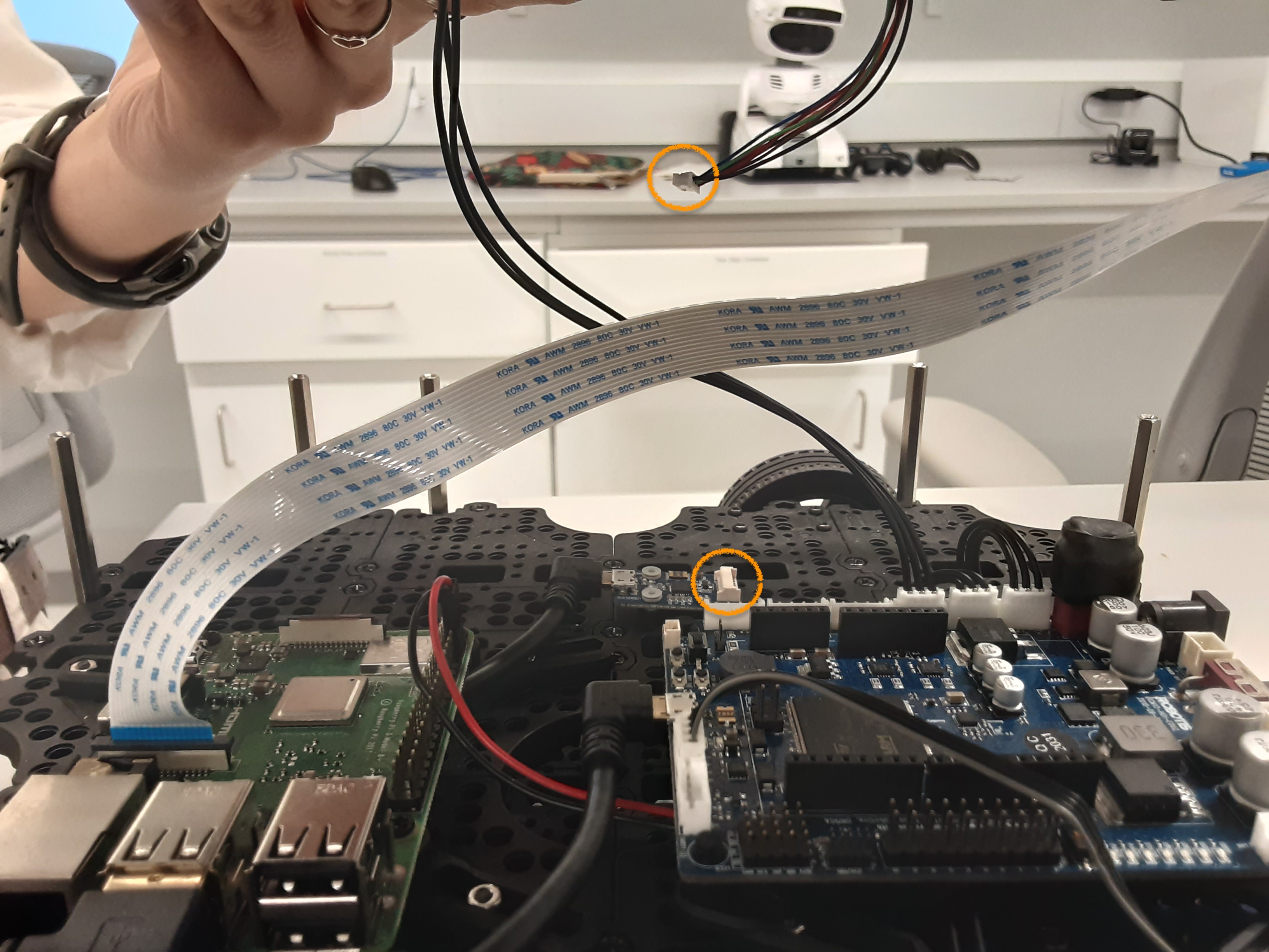
Once the top layer of the Turtlebot is loose, disconnect the cable that is attached to
the LiDAR. This cable is multi-colored with several pins.
Note: ONLY remove this LiDAR cable in this step.Once the top layer is fully disconnected, flip the top layer upside-down for easy access.
-
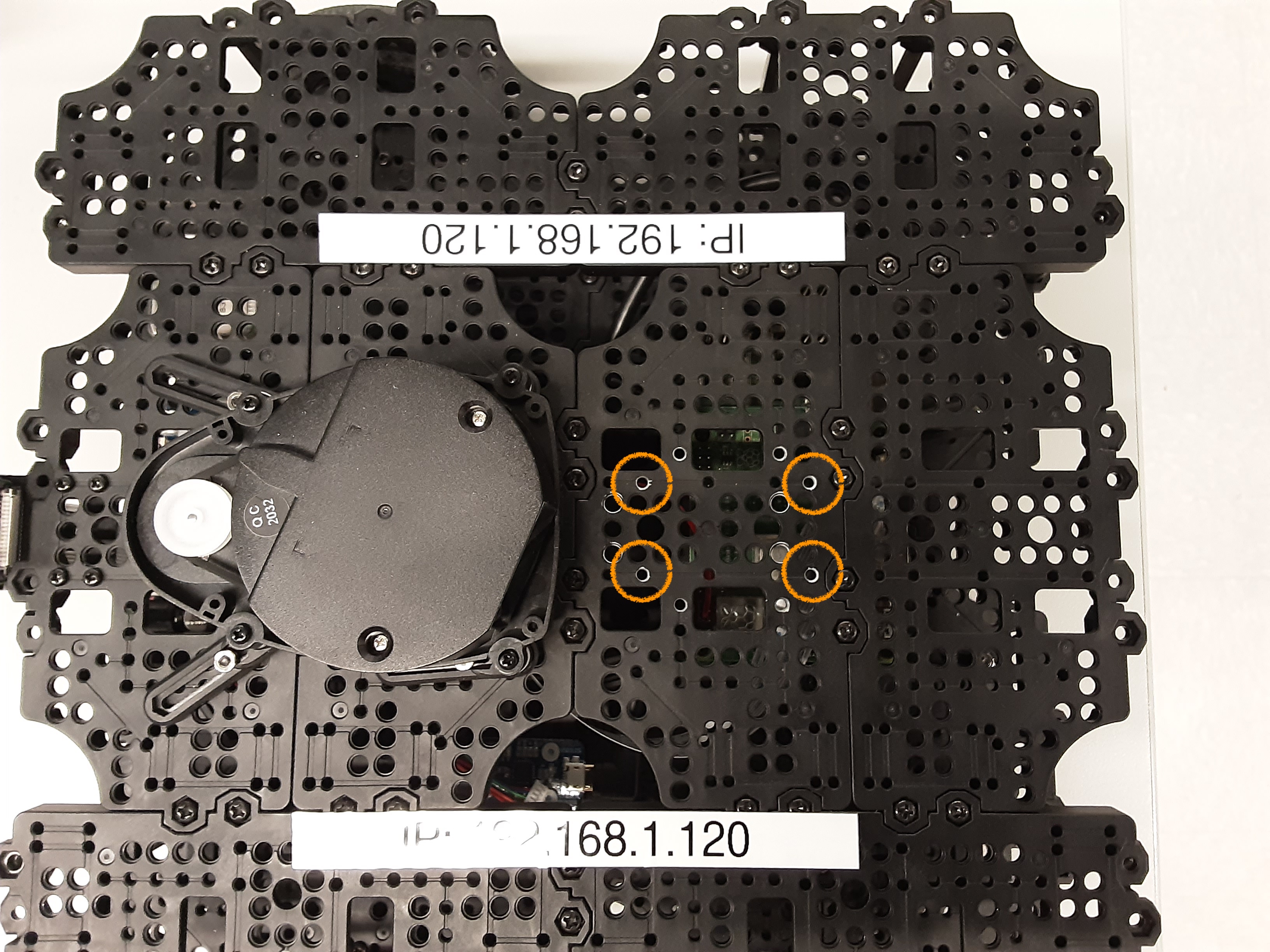
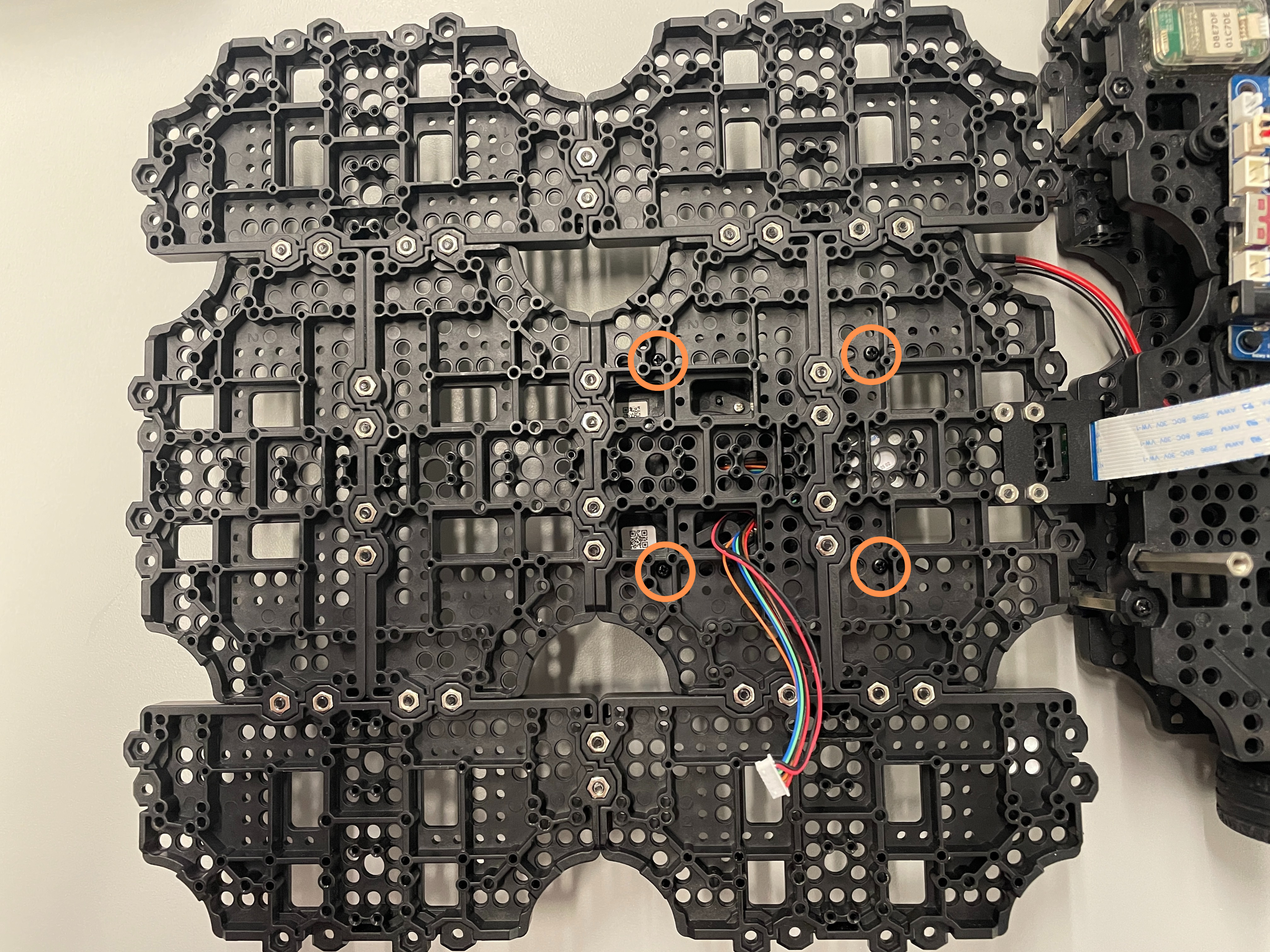
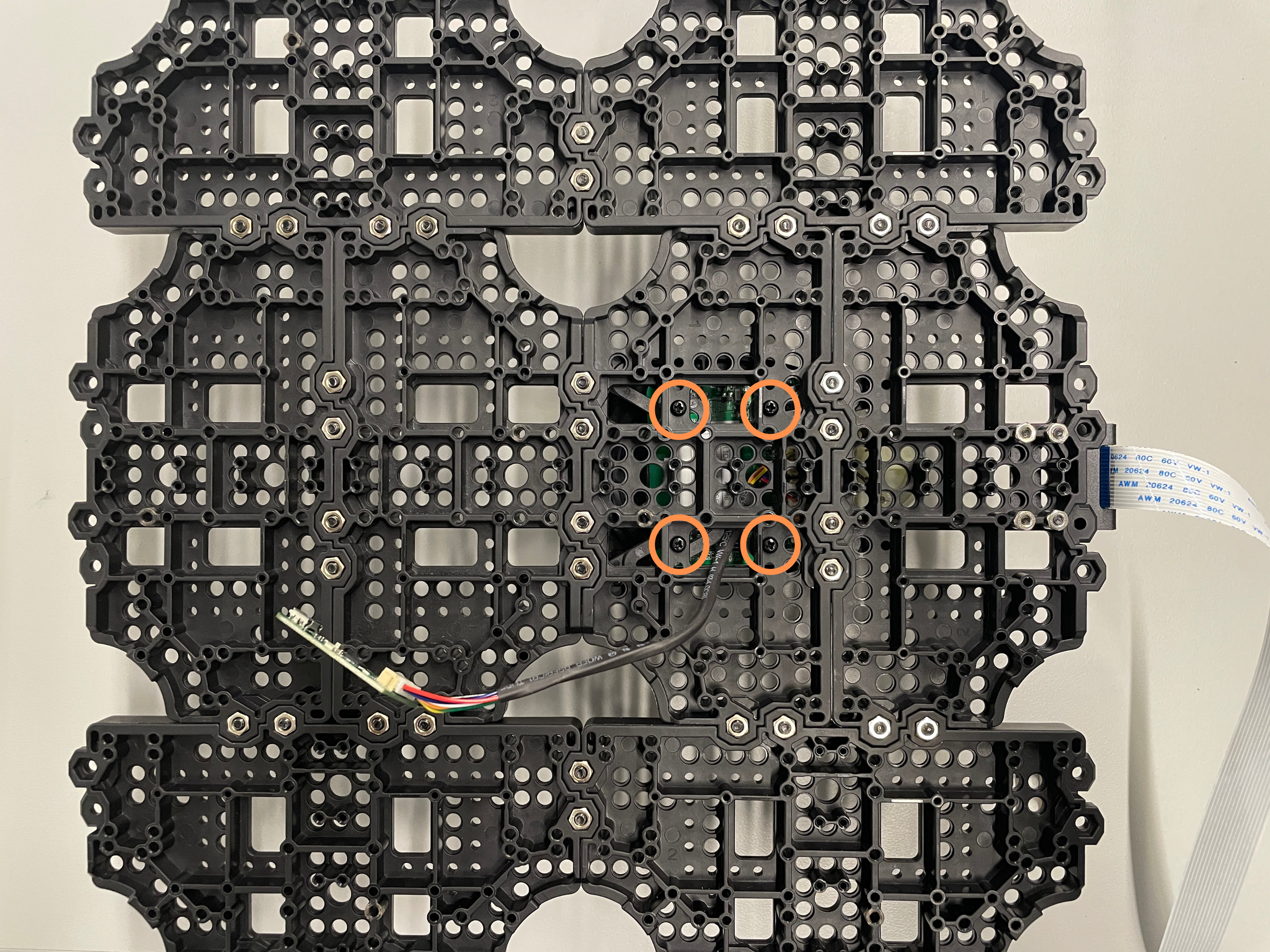
To connect the arm, there are four screws that you will need to insert through
the bottom side
of the top layer that connect to Dynamixel #11. The exact location of the screws
are marked in the picture below. Use an hex/allen key to secure them.
- Once the arm is securely attached, thread the cable connected to DynaMIXEL #11 through the top layer (if not already threaded) and attach the other end to the remaining 3-pin slot on the OpenCR board. It should be the open slot adjacent to the already occupied slots.
- Reconnect the LiDAR cable and re-screw the top layer onto the robot.
To disconnect the arm, follow the same steps as above, but remove the four screws instead and disconnect the DynaMIXEL.
Updating Firmware and Files
Every time the arm is attached or detached, you will need to reconfigure environment variables and update the OpenCR firmware.
For Attaching the Arm
If you are attaching the arm, set the environment variable
OPENCR_MODEL=om_with_tb3 and ensure that OPENCR_PORT=/dev/ttyACM0 in the
~/.bashrc file.
Source the file and update the firmware with:
$ source ~/.bashrc$ cd ~/opencr_update && ./update.sh $OPENCR_PORT $OPENCR_MODEL.opencrFor Detaching the Arm
If you are detaching the arm, set the environment variable
OPENCR_MODEL=waffle and ensure that OPENCR_PORT=/dev/ttyACM0 in the
~/.bashrc file.
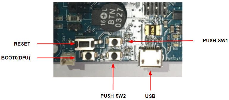
Enter the OpenCR board into firmware recovery mode by pressing and holding SW2, and simultaneously pressing RESET (you will need to remove the top layer of the turtlebot in order to access those OpenCR buttons). If you want to read more about the OpenCR bootloader, please refer to this page in the OpenCR 1.0 manual.
Source the file and update the firmware with:
$ source ~/.bashrc$ cd ~/opencr_update && ./update.sh $OPENCR_PORT $OPENCR_MODEL.opencrInstalling RPLIDAR-A1
Physical Installation
Follow these steps below:
- Remove the top layer of the the Turtlebot. There are 10 screws around the perimeter of the top layer that you will need to remove with a Phillips head / cross screwdriver.
-
Once the top layer of the Turtlebot is loose, disconnect the cable that is attached to
the LiDAR. This cable is multi-colored with several pins.
Note: ONLY remove this LiDAR cable in this step.
-
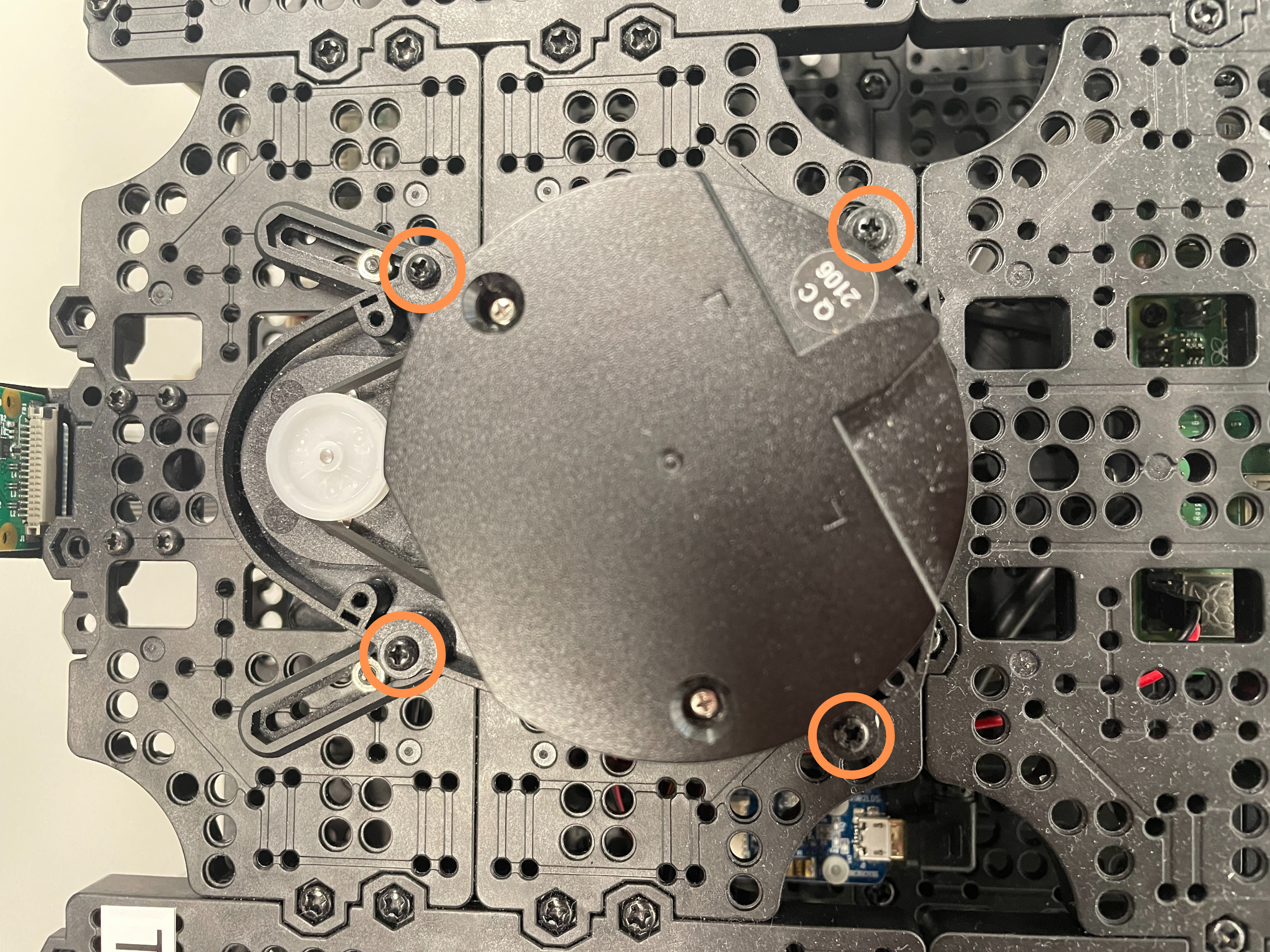
Remove the old LiDAR by unscrewing the four screws around the perimeter of the LiDAR.
-
Flip the top layer upside-down for easy access and remove the four screws holding the LiDAR brackets.
-
Screw in a M2.5x12mm screw into the bottom of each of the four brackets.
-
Screw the four brackets back in using the screws you originally removed. The exact locations of the screws are marked in the picture below.
-
Screw in the four standoffs included with the RPLiDAR to the screws attached to the brackets.

- Plug in the included connecter to the RPLiDAR and slide the cable through the top layer.
- Screw the RPLiDAR into the standoffs using the included screws.
- Plug in the RPLiDAR cable into one side of the green board included with the LiDAR and plug the Micro USB cable from the TurtleBot into the other side.
- Re-screw the top layer onto the robot.
Updating Files
Set the environment variable LDS_MODEL=LDS-01 in the ~/.bashrc file.
Reimaging
Uploading New Image
TurtleBots 1-12 should already have the new image uploaded which supports the RPLiDAR. If for some reason you need to upload the image again follow these steps below:
- Remove the top layer of the the Turtlebot. There are 10 screws around the perimeter of the top layer that you will need to remove with a Phillips head / cross screwdriver.
- Remove the microSD card from the Rasberry Pi.
- Retrieve the image from Intro Robo L03 laptop in the HRI Lab. The file is called `tb3.img` and can be found in the home directory.
- Plug the microSD card into a computer.
-
To identify the microSD card, in a terminal window run:
It will most likely appear as$ lsblk/dev/sda. -
To upload the new image to the microSD card run:
Make sure to replace$ sudo dd if=/path/to/your/downloads/tb3.img of=/dev/sda bs=4M status=progress/path/to/your/downloads/tb3.imgwith the actual file path to your image download. Also replace/dev/sdawith the actual name of your microSD card if it is different.Note: It may be better to upload a new image using Raspberry Pi Imager - To ensure all changes have been physially written to your microSD card run:
sudo sync - Set the environment variable
ROS_HOSTNAME={IP_ADDRESS_OF_RASPBERRY_PI_3}in the~/.bashrcfile.
Creating New Image From Scratch
- Follow the SBC setup instructions for ROS Kinetic from the TurtleBot3 manuel up to but no including section 3.2.7 about installing an LDS-02 LiDAR.
-
Install the RPLiDAR driver and update the TurtleBot3 package with:
$ sudo apt update $ sudo apt install libudev-dev $ cd ~/catkin_ws/src $ git clone https://github.com/Slamtec/rplidar_ros.git $ cd ~/catkin_ws/src/turtlebot3 && git pull $ rm -r turtlebot3_description/ turtlebot3_teleop/ turtlebot3_navigation/ turtlebot3_slam/ turtlebot3_example/ $ cd ~/catkin_ws && catkin_make $ echo 'export LDS_MODEL=RPLIDAR-A1' >> ~/.bashrc -
Modify the TurtleBot3's LiDAR launch file to use the RPLiDAR-A1 with:
$ sed -i.bak 's|</launch>| <group if = "$(eval lds_model == '\''RPLIDAR-A1'\'')">\n <include file="$(find rplidar_ros)/launch/rplidar_a1.launch" />\n </group>\n</launch>|' ~/catkin_ws/src/turtlebot3/turtlebot3_bringup/launch/turtlebot3_lidar.launch -
Modify the RPLiDAR-A1's launch file to have "frame_id" value of "base_scan" instead of "laser" with:
$ sed -i 's/frame_id" type="string" value="laser"/frame_id" type="string" value="base_scan"/g' ~/catkin_ws/src/rplidar_ros/launch/rplidar_a1.launch
$ sudo dd if=/dev/sda of=/path/to/your/downloads/tb3.img bs=4M status=progress/dev/sda with the actual name of your microSD card if it is different.
Also replace /path/to/your/downloads/tb3.img with your desired file path and file name.
Common Errors During Setup
Firmware Recovery Mode and Device Firmware Update for OpenCR Board
We found the firmware recovery mode not clearly detailed in the Turtlebot3 manual. Here are the steps for firmware recovery:
- Push and hold SW2
- Press RESET
- Release SW2
- Arduino code should upload successfully with
jump_with_fw
Firmware recovery is different from device firmware update (DFU), where the steps are:
- Push and hold BOOT
- Press RESET
- Release BOOT
Troubleshooting /dev/ttyACM0 Connection Issues
If the /dev/ttyACM0 port isn't found or running bringup on the Pi is hanging:
- Make sure
$OPENCR_MODELis correct (wafflefor no arm,om_with_tb3for arm) - Disconnect and reconnect the USB cable connecting the Pi and OpenCR board
- Enter firmware recovery (SW2 + RESET)
- Reinstall the firmware with ./update.sh $OPENCR_PORT $OPENCR_MODEL.opencr (see more detailed steps above in the prior section on attaching/detaching the arm)
- [If the above doesn’t work] Restart
roscore - [If the above doesn’t work] Reupload the sketch using the Arduino IDE (install instructions) in
Examples > OpenCR > Etc > usb_to_dxlto the OpenCR board (which you'll need to directly connect to your computer)
If the hydro rosserial / groovy Arduino error appears:
- Configure the arm motors as described in the previous section on attaching/detaching the arm
- Enter firmware recovery (SW2 + RESET)
- Reinstall the firmware with ./update.sh $OPENCR_PORT $OPENCR_MODEL.opencr
- Set up the wheel motors by uploading the sketch using the Arduino IDE (install instructions) in
Examples > TurtleBot3 > turtlebot3_setup > turtlebot3_setup_motorto the OpenCR board (which you'll need to directly connect to your computer)