Turtlebot4 Assembly & Setup
A Word of Caution
This page is NOT intended for student use. This page is designed for course staff to build and maintaining the turtlebots. If you are a student, please ensure you have permission from course staff before making any of the changes detailed on this page to any of the turtlebots.
Turtlebot4 Assembly & Setup
- Initial Turtlebot4 Setup
- Re-Imaging the RaspberryPi
- Attaching the OpenManipulatorX Arm
- Software Setup for OpenManipulatorX Arm
Initial Turtlebot4 Setup
This initial Turltlebot4 setup is meant to take a new Turtlebot4 or a recently re-imaged Turtlebot4 and set it up for use in the course. Follow these steps to set up the Turtlebot4:
- Power off the robot and re-image the RaspberryPi SD card
-
Power on the robot and connect your computer to the robot in Access Point mode
- Place the robot on a charger to power it on.
- Wait for the robot to play the "chime" sound and for it to display its IP address
10.42.0.1on the digital display. - On your computer, connect to the Wi-Fi network named "Turtlebot4" (password:
Turtlebot4).
-
ssh into the robot
- Open a terminal on your computer.
- ssh into the robot:
ssh ubuntu@10.42.0.1 - When prompted, enter the password:
turtlebot4.
-
Connect the robot to the
intro-roboWi-Fi network- In a terminal session on your computer that's already ssh'd into the robot, run the Turtlebot4 setup tool:
turtlebot4-setup- For more information on using the Turtlebot4 setup tool, here's a link to the page explaining the Turtlebot4 setup tool in detail.
- Navigate to the Wi-Fi Setup menu within the Turtlebot4 setup tool and make the following changes:
- Wi-Fi Mode: Client
- SSID: intro-robo
- Password: (ask course staff for network password)

- At the bottom of the Wi-Fi Setup menu page, hit Save.
- Back at the main menu, hit Apply Settings, double check the settings you've changed, and select Yes to apply them.
- You'll now need to wait for the robot to reboot, make the "chime" noise, and connect to the
intro-roboWi-Fi network. - Once the robot has rebooted, it should connect to the
intro-roboWi-Fi network. Check to make sure the IP address listed on the digital display matches the one listed in the Turtlebot4 status spreadsheet.
- In a terminal session on your computer that's already ssh'd into the robot, run the Turtlebot4 setup tool:
-
Ensure the Create base is up-to-date
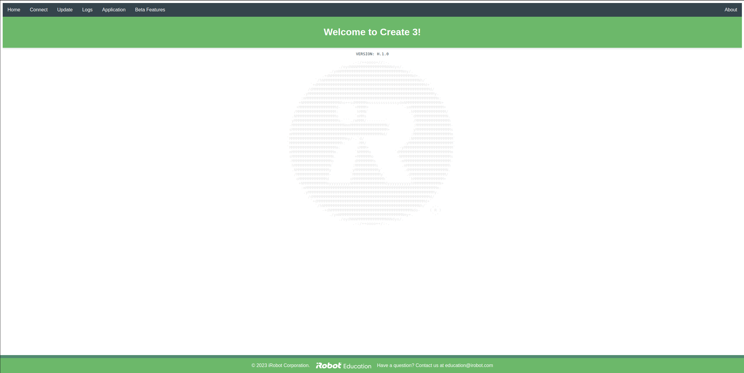
- Access the Create webserver (see image below) by opening a web browser and navigating to
[robot-ip-address]:8080: - Navigate to the Update tab on the top navigation bar.
- Check the firmware version, you should see something like
H.1.2on the Update page. If the firmware version isH.2.6, you do not need to update the firmware, if it is a version less than that, you will need to update it. - If you need to update the Create firmware (version <
H.2.6), follow these steps:- Download the latest Create 3 firmware version for ROS2 Humble on the Create 3® software releases page - for this course we're currently using
H.2.6. - Upload the new firmware file in the Create webserver "Update" tab and press the green button below to upload it to the Create base.
- Wait for the software to be installed, for the robot to reboot, and for it to play the "chime" noise.
- Now, check to see if the new software version has updated by refreshing the Create webserver's Update page, and you should see the newly downloaded version displaying on the page (
H.2.6).
- Download the latest Create 3 firmware version for ROS2 Humble on the Create 3® software releases page - for this course we're currently using
- Access the Create webserver (see image below) by opening a web browser and navigating to
-
Update the RaspberryPi
- On your computer, ssh into the robot (password:
turtlebot4):ssh ubuntu@[robot-ip-address] - Update the RaspberryPi by running the following commands:
sudo apt update
sudo apt upgrade -y
- On your computer, ssh into the robot (password:
-
Set up the Turtlebot4's Discovery Server network configuration
- If you're not already, on your computer, ssh into the robot (password:
turtlebot4):ssh ubuntu@[robot-ip-address] - Run the Turtlebot4 setup tool:
turtlebot4-setup - Navigate to the ROS Setup menu
- Enter the Bash Setup menu and execute the following:
- Change the ROBOT_NAMESPACE to /tb## where the ## represents the two-digit number of the robot. For example, if you're setting up TB 04, you'll set ROBOT_NAMESPACE to /tb04 or if you're setting up TB 11, you'll set it to /tb11.
- Change the ROS_DOMAIN_ID to the two-digit number of the robot. For example, 04 for TB 04 or 11 for TB 11.
- Change the TURTLEBOT4_DIAGNOSTICS to Disabled.
- Press Save.

- Enter the Discovery Server menu and execute the following:
- Change Enabled to True.
- Change the Onboard Server - Server ID to the the two-digit number of the robot. For example, 04 for TB 04 or 11 for TB 11.
- Press Save.

- Press Esc to go back to the main menu.
- Back at the main menu, hit Apply Settings, double check the settings you've changed, and select Yes to apply them.
- Exit the Turtlebot4 setup tool.
- If you're not already, on your computer, ssh into the robot (password:
-
Finish Applying Settings & Restart ROS2 Daemon
- In your terminal (still ssh'd into the robot) execute the following commands one at a time to finish applying the discovery server settings and restart the ROS2 daemon:
sudo systemctl daemon-reload && sudo systemctl start turtlebot4 turtlebot4-source ros2 daemon stop; ros2 daemon start - Wait for the robot to play the "chime" noise.
- In your terminal (still ssh'd into the robot) execute the following commands one at a time to finish applying the discovery server settings and restart the ROS2 daemon:
-
Check to Ensure Robot is Publishing to ROS2 Topics According to the New Settings
- In your terminal (still ssh'd into the robot), list the ros topics currently visible from the robot by running the following command:
You should see an output similar to the image below (the example below is for TB11, so you can see topics appearing with the prefixros2 topic list/tb11/):
- In your terminal (still ssh'd into the robot), list the ros topics currently visible from the robot by running the following command:
-
Test Discovery Server Settings by Controlling the Robot from your Computer
- Following the instructions on the Physical Turtlebot page to test and ensure that the robot can receive commands from your computer.
-
Set Up Bluetooth Connection with XBox Controller
- Follow the Turtlebot 4 Controller Manual Setup instructions to set up the Bluetooth connection with your Xbox controller.
Re-Imaging the RaspberryPi
If you're either setting up the Turtlebot4 for the first time or you find yourself in a sticky situation where the the Turtlebot4's networking setup isn't working properly (e.g., IP address change, discovery server settings change), you may want to re-image the RaspberryPi. First you'll need to access the SD card in the RaspberryPi.
Removing the SD Card from the RaspberryPi
FIRST before removing the SD card, make sure the Turtlebot4 is OFF.
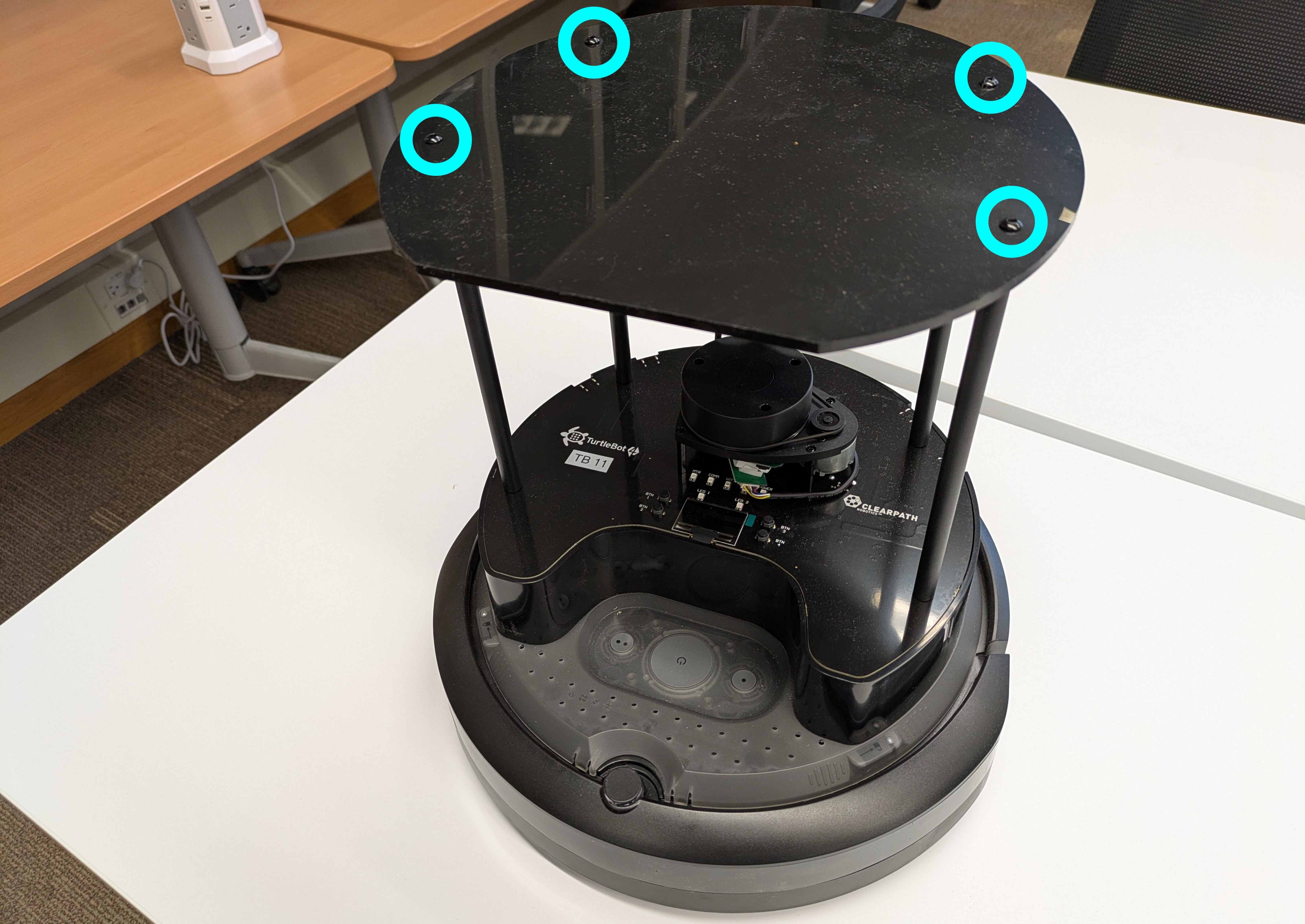
To remove the SD card from the RaspberryPi, you'll first need to remove the top plate of the Turtlebot4 (see below) by removing the 4 screws on the top plate.
Next, remove the 4 vertical posts by unscrewing them with your hand:

Now you can lift the top plate (see photo below) and you can see the SD card coming out of the front of the RaspberryPi:

You'll now need to remove the SD card from the RaspberryPi. There are two ways to do this. One way is to use a pair of needle-nose pliers to gently pull the SD card out of the slot (see below).

If that doesn't work for you, you can also access the SD card by pulling up the black plastic siding surrounding the RaspberryPi. You'll need to remove the 8 screws shown in the image below.

To access the SD card, pull up the black plastic siding in the front of the robot to reveal the SD card (see below). You may need needle nose pliers to pull the SD card out of the RaspberryPi.

Re-imaging the SD Card
Follow the steps below to re-image the SD card (these steps were adapted from the Turtlebot4 User Manual):
- Download the latest Raspberry Pi image
- Find the latest Turtlebot4 RaspberryPi images at http://download.ros.org/downloads/turtlebot4/.
- Download the latest image for the given ROS distribution and robot model (thus far in the course, we have used
turtlebot4_humble_standard_1.0.5). - Extract the zip file to get the
.imgfile.
- Insert the SD card
-
If you're using a microSD to SD card adapter, make sure that it is in the "unlocked" mode by ensuring that the grey switch is slid to the "unlocked" (UP) position and remains up after being inserted in your computer.

-
If you're using a microSD to SD card adapter, make sure that it is in the "unlocked" mode by ensuring that the grey switch is slid to the "unlocked" (UP) position and remains up after being inserted in your computer.
-
Get the name of your SD card
lsblk -d -e7- It should be named something like
sda,sdb, ormmcblk0. - If that command doesn't work, you may need to install the imaging tool
dcfldd:sudo apt install dcfldd
- It should be named something like
-
Get the SD flash script from
turtlebot4_setupand flash the SD card:wget https://raw.githubusercontent.com/turtlebot/turtlebot4_setup/humble/scripts/sd_flash.sh bash sd_flash.sh /path/to/downloaded/image.img- Follow the instructions and wait for the SD card to be flashed.
-
Remove the SD card from your PC
- Don't forget to unmount the SD card before removing it (e.g., through a file manager).
dcfldd:/dev/sda: Read-only file system, check the lock switch on the microSD to SD card adapter (see image above). If it's in the locked position, the OS will treat it as read-only. Slide it to the unlocked position.
Put the SD Card Back in the RaspberryPi
Now, place the SD card back in the RaspberryPi and replace all of the screws, posts, and top plate. You can now turn on the Turtlebot4 and continue with the setup.
Attaching the OpenManipulatorX Arm
Materials

You'll need the following materials to attach the OpenManipulatorX arm to the Turtlebot4 for the first time:
- iFixit precision screwdriver and bit set
- Assembled & tested OpenManipulatorX arm
- Here's a link to the OpenManipulatorX user manual in case you need to assemble a new one.
- Custom 3D printed mounting plate for the OpenManipulatorX arm to attach to the top plate (link to 3D print files)
- Custom laser cut Turtlebot4 top plate (link to laser cut files)
- U2D2 USB communication converter (labeled U2D2_INT)
- U2D2 Power Hub (labeled U2D2 PHB Set)
- Power cable: SMPS DC connector to T plug
- 1ft micro USB to USB-A cable
- Shorter 3-wire JST cable (to connect U2D2 and U2D2 Power Hub)
- LiPo battery
- Black velcro strips
- Black cable tie (not pictured above)
-
Nuts and screws:
- 16 M2.5x8mm screws
- 4 M2.5x16mm screws
- 4 M2.5 nuts
- 4 M3x8mm screws
Attaching the OpenManipulatorX Arm
First, attach the custom 3D printed mounting plate to the OpenManipulatorX arm (make sure you're attaching it in the right direction - see image below).
When attaching the mounting plate, ensure that you're feeding the cable through that will connect with the U2D2 Power Hub later on. If the cable hanging out of the base of the arm is from the original OpenManipulatorX assembly (has a longer 3-wire JST cable), remove it and attach the shorter 3-wire JST cable (that Sarah put with the assembly materials).

Once you have the mounting plate in position, detach the back cap of the Dynamixel motor.

Next, cut or bend-cut the two small side panels following the seam. These small panels are designed to be removable for wires to thread from outside of the motor to the inside:

Pop the plug. You can use your finger to pop it out from the other side.

Thread the wire through the center hole.

Use 16 M2.5x8mm screws to attach the mounting plate to the OpenManipulatorX arm with 4 screws on each side.

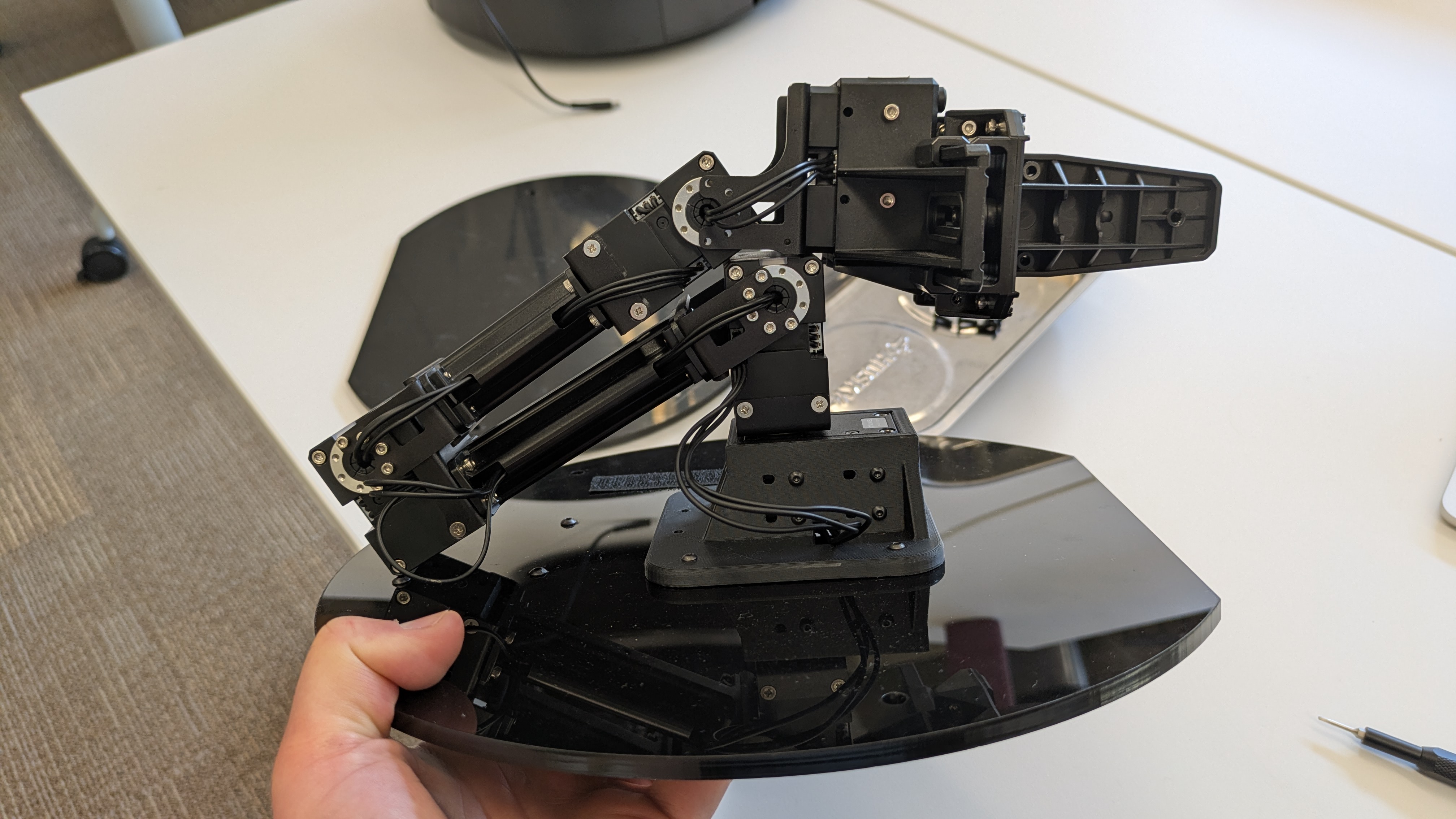
Once you've attached the mounting plate to the OpenManipulatorX arm, the result should look like the image below. Remember to check the orientation of the mounting plate and Dynamixel motor at the base of the arm.

Next, grab the U2D2 and U2D2 Power Hub.

Attach the U2D2 to the U2D2 Power Hub using the 4 black snap rivets that came in the bag with the U2D2.

Your U2D2 and U2D2 Power Hub should now look like the image below:

Attach the white spacers to the U2D2 Power Hub using the 4 spacers and 4 nuts that came in the bag with the U2D2 Power Hub.

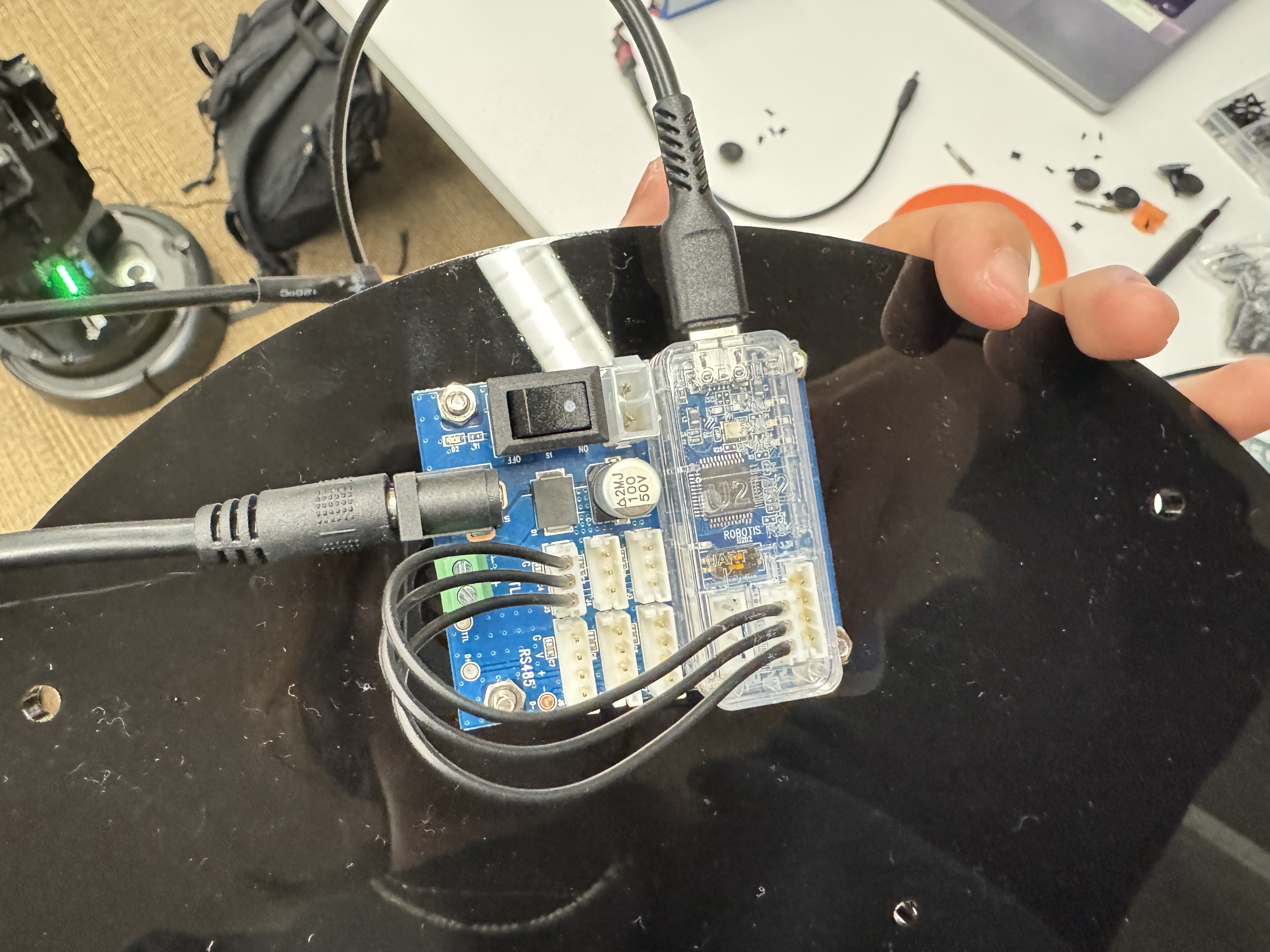
Attach the following cables to the U2D2 and U2D2 Power Hub as shown in the image below:
- 1 foot micro USB to USB-A cable to the U2D2
- 3-wire JST cable from the U2D2 to the U2D2 Power Hub (ensure they're connected exactly as shown in the image below)
- Power cable (SMPS DC connector to T plug) to the U2D2 Power Hub

Attach the U2D2 Power Hub to the custom Turtlebot4 top plate using the 4 M3x8mm screws.

Make sure the switch on the U2D2 board is ON.
Feed the OpenManipulatorX cable through the hole in the Turtlebot4 top plate. Attach the OpenManipulatorX arm to the Turtlebot4 top plate on the OPPOSITE SIDE from the U2D2 Power Hub using the 4 M2.5x16mm screws and 4 M2.5 nuts.
After the 3D printed mount is mounted onto the plate, the wire should come out directly from the motor to the hole on the plate.

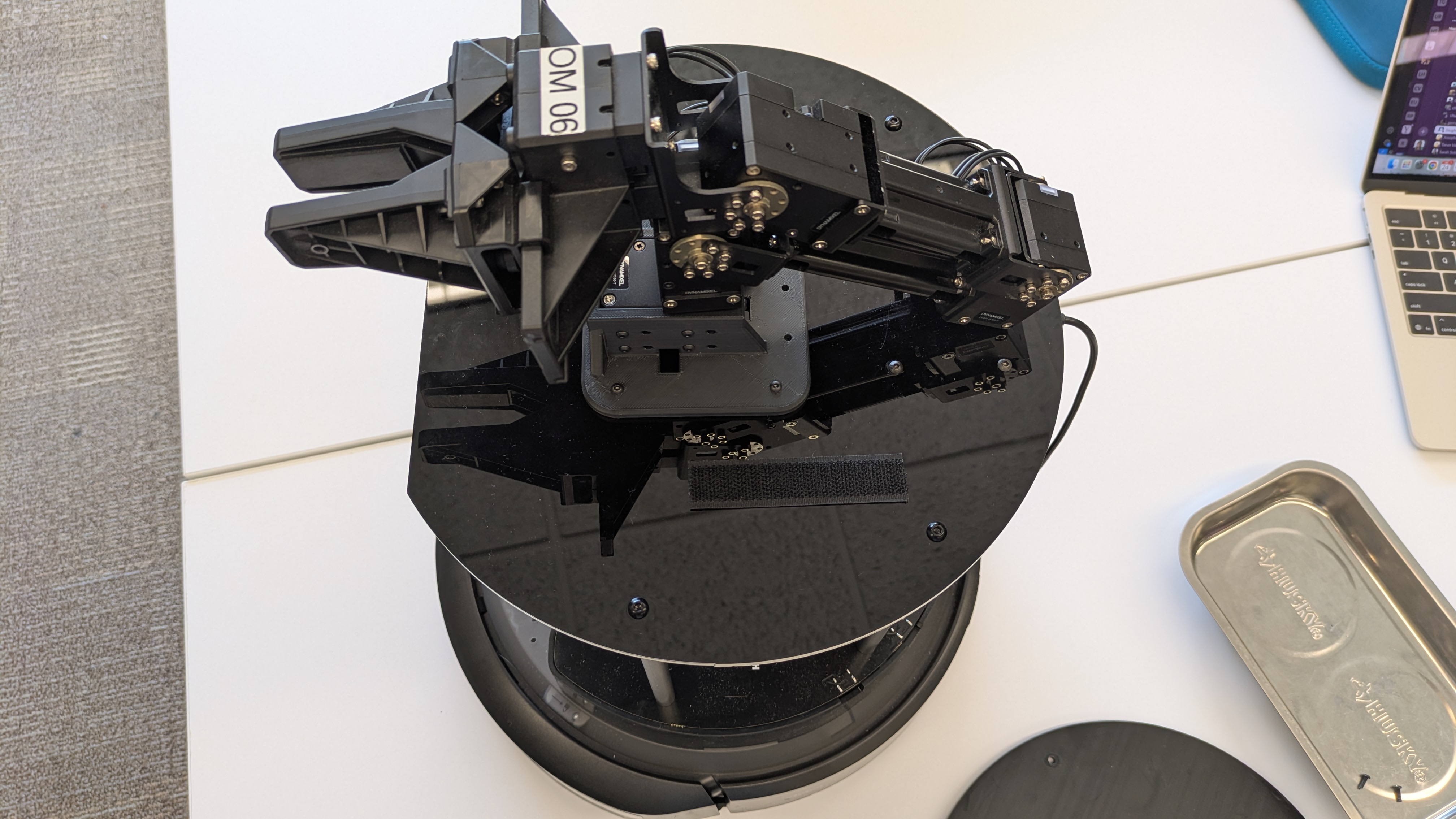
The 3 wire cable from the OpenManipulatorX arm should now be dangling down out of the Turtlebot4 top plate, attach it to the U2D2 Power Hub as shown in the image below.

Unscrew the old top plate for the Turtlebot4 and replace it with the new top plate with the OpenManipulatorX arm and U2D2 Power Hub attached.

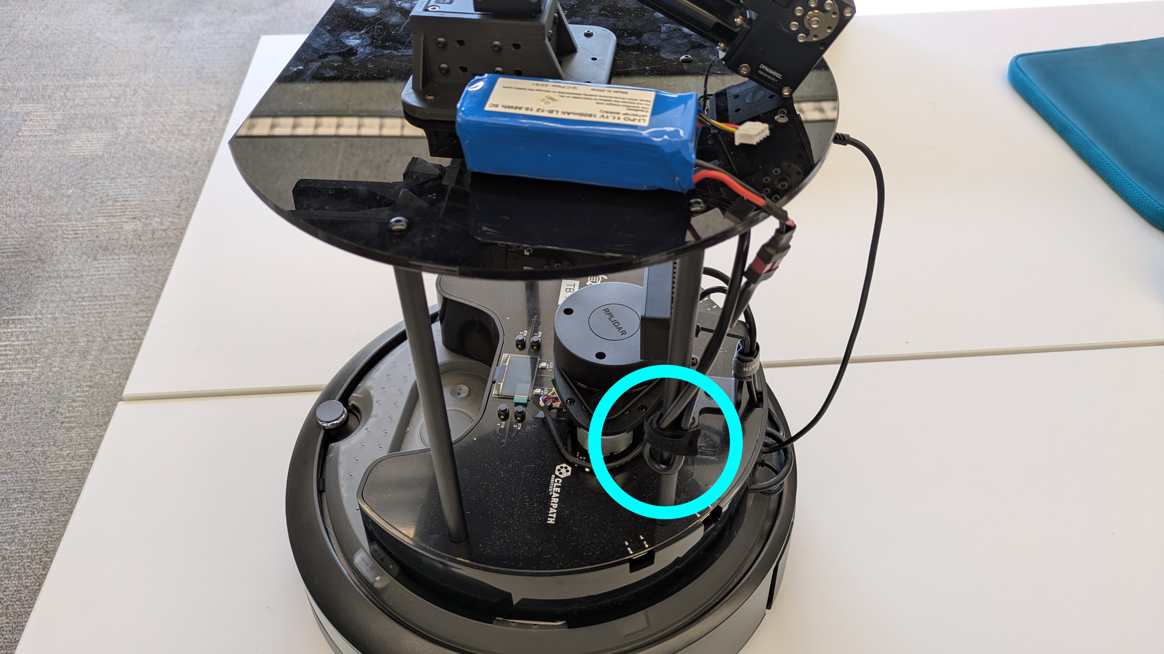
Plug in the USB-A end of the micro USB to USB-A cable into the top left port on the RaspberryPi (see image below).

Attach a hook velcro strip (scratchy side) to the Turtlebot4 top plate as shown in the image below.
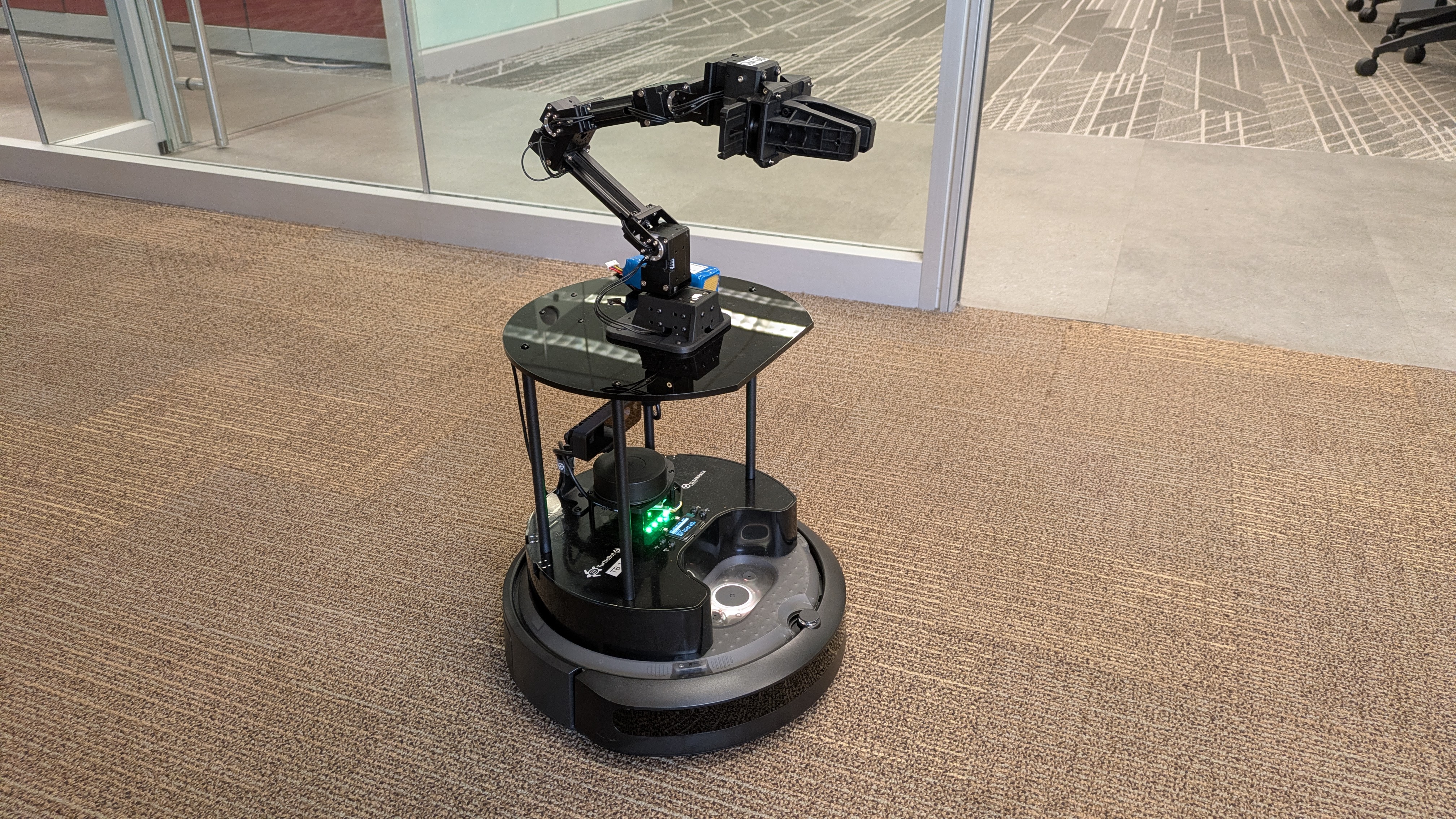
Attach a loop velcro strip (soft side) to the LiPo battery and attach it to the robot. Also attach the LiPo battery to the power cable (T-plug end). Finally, use a cable tie to secure the power cable to one of the vertical posts on the Turtlebot4.
You're hardware setup of the OpenManipulatorX arm attachment to the Turtlebot4 is now complete!
Software Setup for OpenManipulatorX Arm
After attaching the arm, the RaspberryPi will need some additional software to be able to control the arm. Follow these steps (derived from the OpenManipulatorX user manual to set up the software for the OpenManipulatorX arm:
- SSH into the RaspberryPi:
$ set_robot_num [robot_num] $ ssh ubuntu@$ROBOT_IP - Install Debian Packages:
sudo apt install \ ros-humble-ros2-control \ ros-humble-moveit* \ ros-humble-ros2-controllers \ ros-humble-controller-manager \ ros-humble-position-controllers \ ros-humble-joint-state-broadcaster \ ros-humble-joint-trajectory-controller \ ros-humble-gripper-controllers \ ros-humble-hardware-interface \ ros-humble-xacro - Install OpenManipulatorX Packages from Source: The following commands clone the OpenManipulatorX packages from source, installs any dependencies, builds the packages, and sets up the workspace to source automatically when a new terminal is opened.
$ mkdir -p ~/ros2_ws/src $ cd ~/ros2_ws/src $ git clone -b humble https://github.com/ROBOTIS-GIT/DynamixelSDK.git $ git clone -b humble https://github.com/ROBOTIS-GIT/open_manipulator.git $ git clone -b humble https://github.com/ROBOTIS-GIT/dynamixel_hardware_interface.git $ git clone -b humble https://github.com/ROBOTIS-GIT/dynamixel_interfaces.git $ cd ~/ros2_ws $ sudo rosdep init $ rosdep update $ rosdep install --from-paths src --ignore-src -r -y $ colcon build --symlink-install --event-handlers console_direct+ --packages-skip open_manipulator open_manipulator_x_gui $ source ~/ros2_ws/install/setup.bash $ echo 'source ~/ros2_ws/install/setup.bash' >> ~/.bashrcNote:- Every time you build this workspace, you'll need to run the same colcon build command, skipping the
open_manipulator_x_guipackage. We're skipping it because it takes over 15 minutes to install and we don't need it on the RaspberryPi. - If you see the following error you can disregard it (when running rosdep install):
ERROR: the following rosdeps failed to install
  apt: command [sudo -H apt-get install -y ros-humble-gazebo-ros] failed
  apt: Failed to detect successful installation of [ros-humble-gazebo-ros]
- Every time you build this workspace, you'll need to run the same colcon build command, skipping the
- Add Helpful Aliases to the
.bashrc$ echo "alias bringup_arm='ros2 launch open_manipulator_x_bringup hardware.launch.py'" >> ~/.bashrc $ echo "alias start_moveit='ros2 launch open_manipulator_x_moveit_config move_group.launch.py'" >> ~/.bashrc $ source ~/.bashrc - Reduce USB Latency Time: for more info, see the OpenManipulatorX user manual on USB Latency Timer Setting
$ ros2 run open_manipulator_x_bringup create_udev_rules - Test Controlling the OpenManipulatorX Arm: follow the instructions on the Physical Turtlebots resource page Operating the OpenManipulatorX Arm. You should now be able to control the arm and teleoperate its movements.
Acknowledgments
The Turtlebot4 assembly with arm was made possible by Kendrick Xie and Danny Lingen, who helped to configure the Turtlebot4 and integrate the arm. Chi Wang helped significantly with laser cutting the custom top plates and 3D printing the custom mounts for the OpenManipulatorX arm. Willa Yang also helped to refine the Turtlebot4 assembly process.